
- Company
- Press Center
- What is a CAN Bus: Meaning, Advantages, Applications, and More
BLOG
2026.07.20
What is a CAN Bus: Meaning, Advantages, Applications, and More
SHARE
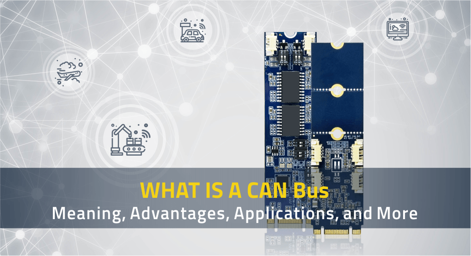
Modern machines are no longer built from isolated parts. In a car, the engine, brakes, battery system, dashboard, sensors, and safety modules all need to exchange information instantly. In factories, robots, controllers, and monitoring devices face the same challenge. This is where CAN Bus comes in. As a key communication protocol, CAN Bus plays an essential role not only in the automotive sector but also in industrial automation, embedded systems, medical equipment, and many other applications.
In this article, we will explore the meaning of CAN bus, how CAN bus works, the key advantages of CAN bus, its common applications, and how Cervoz's CAN bus expansion card helps industrial systems add stable and flexible CAN connectivity.
What is CAN Bus?
Let's start with the basics: a vehicle bus, often referred to simply as a bus, is an internal communication network that connects different electronic components within a vehicle. Now, enter the Controller Area Network, or CAN bus, a specialized type of vehicle bus that allows electronic control units (ECUs) or nodes to communicate with each other directly without relying on a central computer.The CAN bus protocol was first developed by Bosch in the early 1980s and officially introduced in 1986 as a solution for increasingly complex automotive electronics. As more sensors, controllers, and electronic functions were added to vehicles, traditional point-to-point wiring became heavier, more complicated, and harder to manage. CAN bus helped solve this challenge by allowing multiple devices to share the same communication network, making the CAN bus system in vehicle design more organized and scalable.
The effectiveness of CAN bus lies in its message-based communication method. Instead of sending data to a specific device address, each message carries an identifier that defines its meaning and priority. This allows connected nodes to recognize whether a message is relevant to them and helps the network manage communication in an efficient way.
CAN bus, much like RS-485, uses differential signaling to support stable communication in electrically noisy environments, though the two technologies differ in protocol structure and system design. CAN bus also includes defined rules for message format, error handling, and network behavior, which are standardized under the ISO 11898 series. The original ISO 11898 standard was published in 1993 and later reorganized into separate parts for the CAN protocol and physical layer specifications.
| ISO Standard | Main Focus | Simple Explanation |
|---|---|---|
| ISO 11898-1 | CAN data link layer and physical signaling | Defines the core CAN protocol, including message framing, arbitration, error handling, and how data is organized for communication. |
| ISO 11898-2 | High-speed CAN physical layer | Defines the high-speed physical layer used in many automotive and industrial CAN networks. |
| ISO 11898-3 | Low-speed, fault-tolerant CAN physical layer | Defines the low-speed, fault-tolerant physical layer designed for applications where continued operation is important even if wiring faults occur. |
How Does CAN Bus Work?
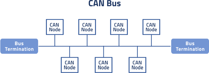
A CAN bus network is made up of multiple connected nodes, such as engine control units, sensors, actuators, gateways, or industrial controllers. In a vehicle, these nodes are often called ECUs, or Electronic Control Units. Instead of using separate wiring for every signal, each ECU connects to the shared CAN bus and exchanges messages with other devices on the same network.
CAN bus uses message-based communication. This means a message is not sent to one fixed destination address. Instead, every node on the bus can receive the transmitted frame, and each node checks the message identifier to decide whether the information is relevant to its own function. This design helps reduce wiring complexity while allowing different systems, such as braking, engine control, temperature sensing, and diagnostics, to share data efficiently.
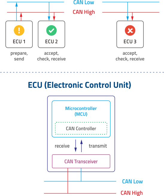
In a typical ECU, three key parts work together to complete CAN bus communication:
ECU Part
Main Role in CAN Bus Communication
Microcontroller
Runs the application logic, such as reading sensor values, controlling actuators, or making system decisions.
CAN Controller
Handles the CAN protocol tasks, including message framing, filtering, arbitration, and error handling.
CAN Transceiver
Converts digital signals from the CAN controller into physical CAN signals on the bus, and converts received bus signals back for the controller.
When an ECU needs to send CAN bus data, the microcontroller prepares the information, such as vehicle speed, engine temperature, braking status, or sensor feedback. The CAN controller then formats this information into a CAN message frame. A standard CAN frame includes fields such as an identifier, control information, data payload, CRC, acknowledgment, and end-of-frame bits.
After the message is prepared, the CAN transceiver drives the differential signal onto the CAN High and CAN Low wires. CAN networks commonly use a twisted two-wire bus, where the same signal is carried in opposite voltage directions. This differential signaling helps improve noise resistance, which is especially useful in vehicles, industrial machines, and other electrically noisy environments.
One important feature of CAN bus is arbitration. Because multiple nodes share the same communication line, more than one node may try to transmit at the same time. CAN solves this by using the message identifier to determine priority.
During arbitration, the message with the lowest numerical arbitration ID has the highest priority and continues transmitting, while lower-priority messages wait and try again when the bus becomes available. This allows time-sensitive data, such as braking, engine control, or safety-related signals, to be transmitted without being delayed by less urgent information.
Different Versions of CAN Bus
As CAN bus technology has evolved, different CAN variants have been developed to support different data rates, payload sizes, fault-tolerance needs, and system architectures.CAN bus types can be understood in two ways. Low-speed CAN and high-speed CAN mainly describe the physical communication layer, such as wiring, signaling, and transmission speed. Classical CAN, CAN FD, and CAN XL, on the other hand, describe different protocol generations, including how data is framed, how much data can be carried, and how fast information can be transferred.
Despite these differences, all CAN types are based on the same core concept: multiple devices are connected to a shared bus, and they exchange data through message-based communication instead of direct point-to-point wiring.
Low-speed CAN, also known as fault-tolerant CAN, is commonly associated with ISO 11898-3. It is designed for lower data rates, typically up to 125 kbit/s, and is often used in applications where continued operation is more important than high-speed communication. Because it can keep working under certain wiring fault conditions, low-speed CAN is commonly used for less time-critical in-vehicle functions such as body electronics, comfort control, door modules, lighting, and seat control systems.
High-speed CAN is the most widely used CAN physical layer in automotive and industrial systems. Based on ISO 11898-2, it is commonly used with Classical CAN communication up to 1 Mbit/s. This makes it suitable for systems that need fast and reliable real-time data exchange, such as powertrain control, chassis systems, industrial controllers, and embedded equipment. Newer ISO 11898-2 physical-layer updates also support higher bit rates for CAN FD data transmission, depending on the network layout and transceiver design.
CAN FD, short for CAN Flexible Data-Rate, was developed to increase both communication efficiency and payload capacity. Compared with Classical CAN, which carries up to 8 bytes of data per frame, CAN FD can carry up to 64 bytes. It also supports two bit-rate phases: a normal arbitration phase and a faster data phase. This makes CAN FD useful for modern ECUs, diagnostics, battery systems, high-rate sensors, and applications that need to transfer more data without moving to a completely different network technology.
CAN XL, or CAN eXtended Length, is the next step in CAN development. It is designed for much higher data throughput while keeping many of the advantages of CAN, such as priority-based communication and robust networking. CAN XL supports data fields of up to 2048 bytes and can reach data rates up to 20 Mbit/s when suitable transceivers and network designs are used. This makes it useful for vehicle gateways, zonal architectures, advanced sensors, and systems that need to connect traditional CAN networks with higher-bandwidth communication architectures.
| CAN Type | Typical Standard / Reference | Max Payload | Typical Speed Range | Key Characteristics | Common Use Cases |
|---|---|---|---|---|---|
| Low-speed CAN / Fault-tolerant CAN | ISO 11898-3 | Up to 8 bytes | Up to 125 kbit/s | Lower speed, fault-tolerant physical layer, supports continued operation under certain wiring faults | Body electronics, comfort control, door modules, seat control |
| High-speed CAN / Classical CAN | ISO 11898-2 physical layer, ISO 11898-1 data link layer |
Up to 8 bytes | Up to 1 Mbit/s for Classical CAN | Widely used, reliable, suitable for real-time control communication | Powertrain, chassis control, industrial equipment, embedded controllers |
| CAN FD | ISO 11898-1 with CAN FD support |
Up to 64 bytes | Arbitration phase usually up to 1 Mbit/s; faster data phase depends on transceiver and network design | Larger payload and flexible data rate for higher throughput | Modern vehicle ECUs, diagnostics, battery systems, high-rate sensors |
| CAN XL | ISO 11898-1:2024, CiA 610 development references |
Up to 2048 bytes | Up to 20 Mbit/s, depending on transceiver and topology | Much larger data field, higher throughput, designed for data-intensive systems | Vehicle gateways, zonal architectures, advanced sensors, Ethernet-related integration |
Benefits of Using CAN Bus


Applications of CAN Bus
CAN bus was originally developed for vehicles, but its reliable communication design has made it useful in many other industries. Anywhere multiple electronic devices need to exchange data quickly and consistently, CAN bus can provide a practical communication solution. Today, it is commonly found in automotive systems, industrial equipment, medical devices, energy systems, heavy-duty machinery, transportation, and embedded applications.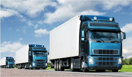
Automotive Electronics
The application scope of CAN bus in vehicles is extensive, ranging from engine control and instrument panels to safety systems and entertainment units. Its high-speed transmission and reliability enable real-time communication among various in-vehicle devices, enhancing both driving experiences and vehicle performance.
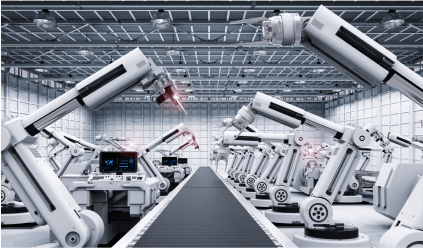
Industrial Automation
In the industrial realm, CAN bus connects a range of automated devices, from robots to production line monitoring systems. This real-time communication capability facilitates efficient collaboration among factory equipment, boosting production efficiency.
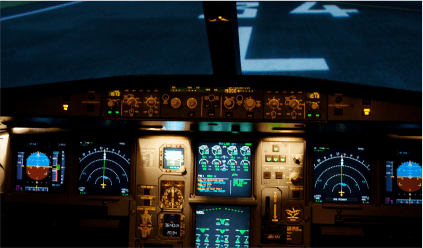
Aerospace and UAVs
CAN bus can also be found in aerospace-related applications such as UAVs, flight control systems, sensors, power modules, and monitoring devices. These systems often require reliable communication between compact electronic modules, making CAN bus a practical choice for distributed control and real-time data exchange.
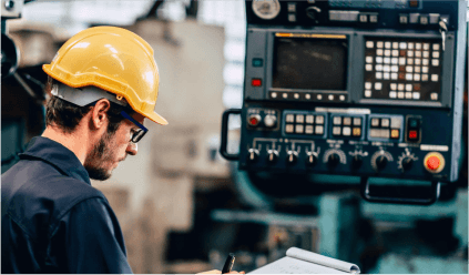
Embedded Systems
CAN bus in embedded systems facilitates connections among diverse devices, such as smart home systems, medical devices, and consumer electronics. This connectivity enables seamless data exchange and control among devices.
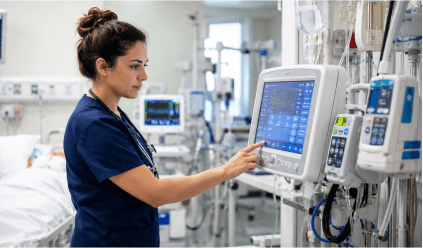
Medical Equipment
Medical equipment often includes multiple internal modules that need to work together accurately and reliably. CAN bus can be understood as the basic communication network, while CANopen is a higher-level protocol built on CAN bus that helps standardize how devices exchange data.
CAN bus and CANopen can be used in systems such as imaging equipment, patient positioning devices, laboratory machines, and motorized medical equipment. They help connect sensors, motors, controllers, displays, and monitoring units through a structured communication network, allowing different parts of the device to exchange status and control data efficiently.
CAN bus and CANopen can be used in systems such as imaging equipment, patient positioning devices, laboratory machines, and motorized medical equipment. They help connect sensors, motors, controllers, displays, and monitoring units through a structured communication network, allowing different parts of the device to exchange status and control data efficiently.

Railway and Transportation Systems
In railway and transportation systems, CAN bus can support communication between onboard control units, door systems, lighting, HVAC systems (Heating, Ventilation, and Air Conditioning), diagnostic devices, and monitoring equipment. Because these systems often contain many distributed electronic modules, CAN-based communication helps simplify wiring, improve coordination, and support stable long-term operation in demanding vehicle environments.

Marine Systems
In marine applications, CAN bus is commonly seen through CAN-based networks such as NMEA 2000. It can be used to connect engine control, power, and navigation systems, plus vessel monitoring devices and onboard electronics. Since boats and ships often contain electronic systems spread across different areas, a shared communication network helps reduce wiring complexity and gives operators better visibility into vessel status.

Energy and Power Systems
CAN bus is also used in many energy-related applications, including battery management systems, energy storage systems, power converters, EV charging equipment, and inverter-related communication. These systems often need to monitor voltage, current, temperature, state of charge, fault status, and operating conditions. CAN bus helps different modules exchange this information efficiently, supporting safer and more stable power management.
FAQs
What is CAN Bus used for?
CAN bus is used to connect multiple electronic devices so they can exchange data through a shared communication network. It is widely used in vehicles, industrial automation, medical equipment, energy systems, heavy-duty machinery, railway systems, marine systems, and embedded devices.Why is CAN bus important in vehicles?
CAN bus is important in vehicles because it allows different ECUs, such as engine control, braking, dashboard, lighting, battery, and safety modules, to communicate in real time. This helps reduce wiring complexity while supporting stable communication between many in-vehicle systems.What are the main advantages of CAN bus?
The main advantages of CAN bus include reliable communication, reduced wiring, strong noise resistance, priority-based message handling, real-time data exchange, and easier system expansion. These features make it suitable for vehicles, industrial equipment, and other systems that require stable device communication.What is the difference between CANH and CANL?
CANH stands for CAN High, and CANL stands for CAN Low. They are the two signal lines used in a CAN bus network. CAN bus uses differential signaling, meaning devices read the voltage difference between CANH and CANL to transmit data more reliably in noisy environments.What is the maximum CAN bus speed?
For Classical high-speed CAN, the maximum bit rate is generally 1 Mbit/s under ISO 11898-2. CAN FD can transmit data faster in the data phase and supports larger payloads, while CAN XL can support data throughput up to 20 Mbit/s depending on the transceiver and network design.What is the difference between CAN and CAN FD?
Classical CAN supports up to 8 bytes of data per frame, while CAN FD supports up to 64 bytes. CAN FD also allows a faster data phase, which helps improve data throughput for modern vehicle ECUs, diagnostics, battery systems, and higher-data applications.How many devices can connect to a CAN bus?
There is no single fixed number for every CAN bus system. The number of devices depends on factors such as transceiver capability, bit rate, cable length, bus loading, termination, and overall network design. In practical systems, engineers must design the bus so signal quality and timing remain stable across all connected nodes.Explore Cervoz CAN Bus Module Solutions for Industrial Connectivity
As communication demands continue to grow across automotive, industrial automation, and embedded systems, CAN bus remains a reliable technology for stable device-to-device data transfer. Cervoz supports these needs with our CAN bus PCIe expansion card solutions, which can function as practical CAN bus modules for industrial computers and embedded platforms.Our latest CAN FD expansion card also earned an Embedded Award 2026 nomination and the Community Choice Award at Embedded World 2026, highlighting its value for reliable communication in compact embedded systems. By adding a dependable CAN bus interface through a PCIe expansion design, you can improve system connectivity, device control, and long-term communication reliability. Contact us to for more information or explore our latest CAN bus product offerings and bring more innovation and reliability to your industrial projects.
